


O ventilated facade It is a technical system consisting of several layers: a structural wall, thermal insulation, a metal substructure, and cladding material. The proper functioning of the entire system depends largely on support structure, the component that bears the loads and maintains the system's flatness.
In practice, the cladding material is only the visible part. The stability and durability of a ventilated facade are determined by how the substructure is designed and sized.
Modern cladding systems mounted on a framework create an air gap between the wall and the cladding, which helps protect the building and stabilize the thermal performance of the facade.
The Role of the Support Structure in a Ventilated Facade System
The substructure has four main roles:
1. supports the weight of the system
2. distributes wind loads to the building structure
3. creates the ventilation space
4. ensures the facade is level
A typical ventilated facade system may have the following weights:
| Component | Approximate weight |
|---|---|
| WPC panel | 12–20 kg/sq m |
| aluminum substructure | 5–10 kg/sq m |
| consoles + accessories | 2–5 kg/sq m |
The total weight often reaches:
20–30 kg/sq m
In the case of ceramic or fiber-cement panels, the weight may exceed:
40–50 kg/sq m
These values determine the sizing:
- profile thicknesses
- the distance between the brackets
- the type of anchor used.
Recommended minimum thickness for aluminum profiles
In professional projects involving ventilated facade, the aluminum profiles must be sized to ensure sufficient rigidity for the installed panels.
In most systems used in Europe, profiles with the following thicknesses are used:
| Profile Type | Recommended thickness |
|---|---|
| secondary profile | 2 mm |
| vertical structural profile | 2–2.5 mm |
| heavy-panel systems | more than 2.5 mm |
Thinner profiles of 2 mm may cause over time:
- wind-induced vibrations
- local deformations
- stress in the panel fasteners.
Based on experience in construction, structural rigidity is one of the most important factors for the stability of a ventilated facade.
The correct distance between brackets and profiles
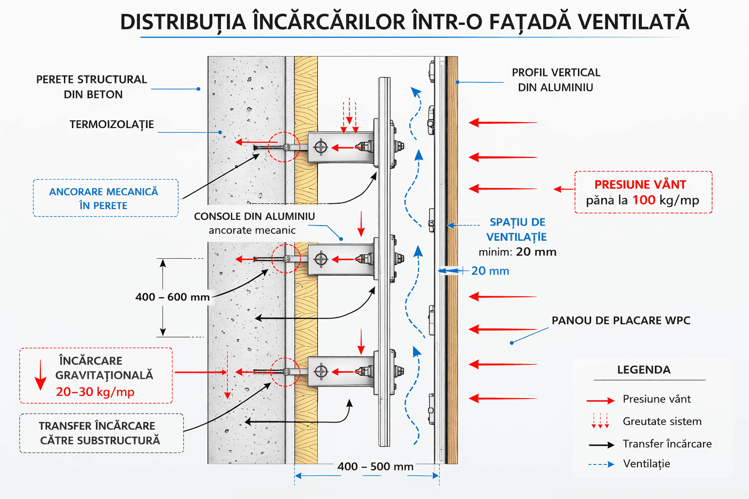
In a ventilated facade, the support structure must be designed to bear both the weight of the system and wind pressure.
The correct sizing of the support structure depends on the distance between the fasteners.
In most ventilated facade systems:
distance between brackets:
400–600 mm
distance between vertical profiles:
400–500 mm
In areas exposed to strong winds or near tall buildings, the distance may be reduced to:
300–400 mm
This uniform distribution of the brackets ensures that loads are properly transferred to the structural wall.
The length of the brackets and their positioning
Brackets are the components that connect the substructure to the building's wall.
Their length depends on:
- the thickness of the thermal insulation
- ventilation space
- the final position of the facade.
In most ventilated systems, the cantilevers range in length from:
80 mm and 200 mm
Consoles are usually made of:
- extruded aluminum
- galvanized steel.
They must be anchored to the building's structure using:
- mechanical dowels
- chemical anchors.
Size of the ventilation space
The air space between the wall and the cladding is the element that determines the operation of a ventilated facades.
In most modern systems, the minimum recommended space is:
20 mm
In projects involving tall facades or large panels, the space can reach:
30–40 mm
This space allows you to:
- air circulation
- drainage of seepage water
- drying of the thermal insulation.
Permissible Tolerances for Substructure Installation
The flatness of the support structure is essential for the proper installation of the panels.
The standard tolerances are:
| Element | Tolerance |
|---|---|
| flatness of the profiles | ±2 mm / 2 m |
| alignment of the brackets | ±3 mm |
| the difference between profiles | max 2 mm |
| deviation on the facade | max 5 mm |
Exceeding these values results in:
- uneven joints
- panel tensioning
- deformations of the cladding.
Simple stiffness test used on a construction site
A quick test used by many installation teams involves checking the structure's rigidity before installing the cladding.
Procedure:
- The support structure is fully assembled
- A lateral force is applied manually to the central area of the profile.
If the profile shows visible deflection or vibration, the structure must be stiffened by:
- adding brackets
- reducing the distance between profiles
- the use of thicker profiles.
How to Recognize a Properly Constructed Support Structure
In a properly constructed ventilated facade, several distinct elements can be observed:
✔ perfectly aligned profiles
✔ Consistent spacing between elements
✔ brackets mechanically anchored to the wall
✔ Continuous ventilation space
✔ Correctly sized fasteners.
When these conditions are met, the system can operate reliably for decades.
Recommended Technical Checks Before Installing the Panels
After the substructure has been fully assembled, but before the cladding panels are installed, it is recommended to perform a technical inspection of the support structure. At this stage, any errors can be corrected without affecting the cladding material.
1. Checking the flatness of the structure
The flatness of the profiles must be checked using a laser level or a straightedge at least 2 meters long.
The recommended tolerance is:
±2 mm over a length of 2 m
More significant deviations can result in:
- uneven gaps between panels
- tightening the fasteners
- deformation of the cladding.
2. Checking the rigidity of the profiles
Vertical profiles must be sufficiently rigid to withstand wind loads.
A simple test frequently used on construction sites involves applying moderate lateral pressure to the center of the profile.
A properly sized profile:
✔ shows no visible vibrations
✔ Does not become permanently deformed
✔ Returns immediately to its original position.
If the profile shows pronounced flexion, it is possible that:
- the profile thickness is insufficient
- the distance between the brackets is too great.
3. Checking the anchoring of the brackets
The brackets must be mechanically fastened to the structural wall.
Check the following:
- the type of anchors used
- anchor depth
- the correct position of the screws.
The following are commonly used for concrete or solid masonry walls:
- mechanical dowels
- chemical anchors.
4. Checking the ventilation space
The space between the wall and the cladding material must be continuous across the entire surface of the facade.
The recommended minimum value is:
20 mm
For tall facades or large panels, the space can be extended to:
30–40 mm
This space allows air to circulate and any moisture to escape.
Technical parameters commonly used in substructure design
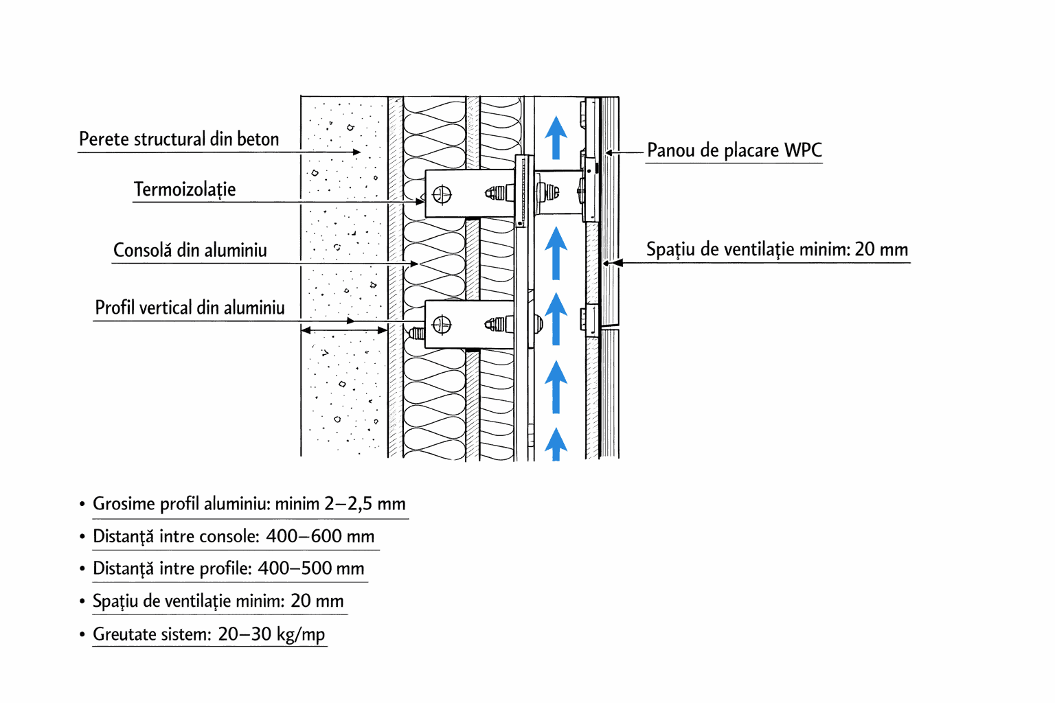
The diagram shows the parameters commonly used in the design of a support structure for a ventilated facade, including the thickness of the aluminum profiles, the distance between the brackets, and the minimum ventilation clearance.
In projects involving ventilated facade, the support structure is designed based on the cladding material, the height of the building, and wind loads.
The following parameters are frequently used in ventilated facade projects:
| Element | Recommended value |
|---|---|
| Aluminum Profile Thickness | minimum 2–2.5 mm |
| Distance between brackets | 400–600 mm |
| Distance between vertical profiles | 400–500 mm |
| Minimum ventilation clearance | 20 mm |
| WPC System Weight | 20–30 kg/sq m |
| Structural flatness tolerance | ±2 mm / 2 m |
These values may vary depending on the project, but they represent the parameters commonly used to design a stable substructure.
A properly sized support structure allows for the precise installation of the panels and ensures the proper operation of the ventilation system behind the cladding.


